Group Assignment (refer to our Group Page)
* Complete your lab's safety training.
* Test runout, alignment, fixturing, speeds, feeds, materials and toolpaths for your machine.
* Document your work to the group work page and reflect on your individual page what you learned.
* Make (design+mill+assemble) something big.
☑ Linked to the group assignment page.
☑ Documented how you designed your object (something big).
☑ Documented how you made your CAM-toolpath.
☑ Documented how you made something BIG (setting up the machine, using fixings, testing joints, adjusting feeds and speeds, depth of cut etc.).
☑ Described problems and how you fixed them.
☑ Included your design files and 'hero shot' of your final product.
Make (design+mill+assemble) something big
History background about My Skills and Knowledge on CNC machine
I like this week assignment, reason being I myself have "played" this kind of CNC machine before. 15 yesrs ago, I was a machine programmer for a CNC machine which is dealing with Solid Surface Material. Given by a 4ft x 8ft material, thickness varies from 5mm to 20mm, I am suppose to design some profiles or even small designs on either counter-top for kitchen and receiption counter, as well as signboard panels for retail shops. Based on this, CNC machine become my very 1st machine to "play" once I joined Singapore Polytechnic FabLab.
Here is my materpiece when I am using CNC machine to make:

Designing using FUSION360 software
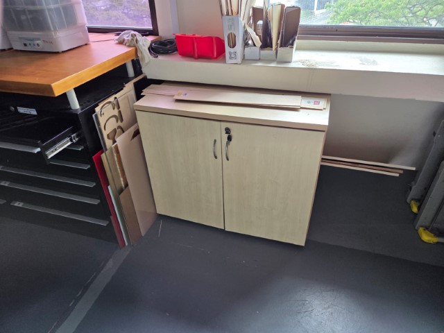
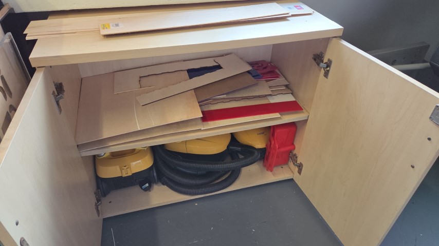
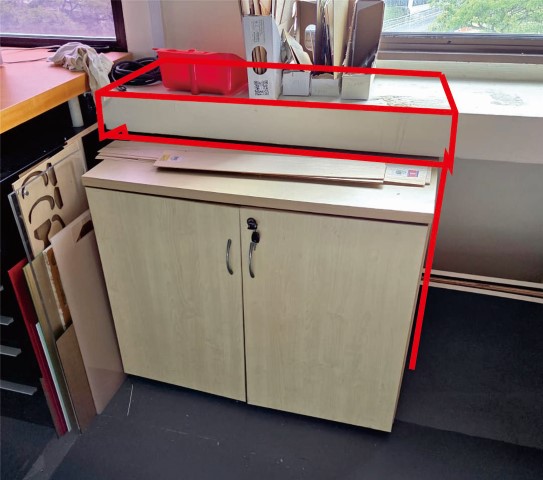
It took me no more than 15 mins to decide what I want to make something big. As shown, I am planning to re-produce a storage unit that stores all the small-piece waste material, either Acrylic, Plywood, or Cardboard.
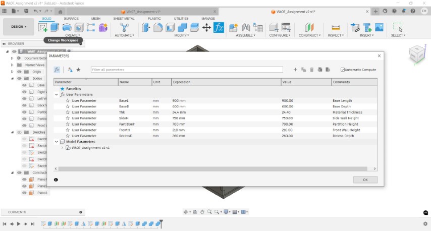
I have taken down all the important parameters to construct the storage unit and enter into the PARAMETERS pop-up page. Within an hour, I have came out with the 3D model of my strorage unit.

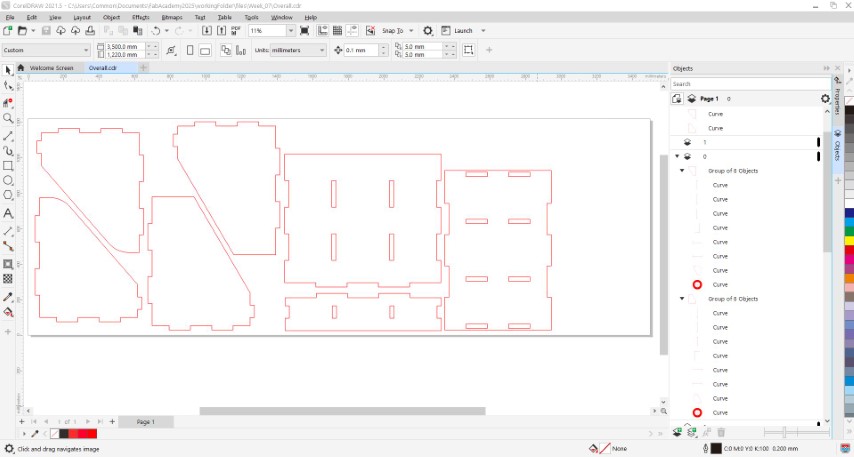
I have exported ALL the individual piece in dxf format and uses CorelDRAW software to arrange my individual piece, as shown below:
There are some steps that we need to do before start using VCrave-PRO to generate G-Code for the CAM toolpaths:
1) Ensure that the KERF value so that the parts that I am going to cut can bit press-fit and hold together. This step we have done when we are dealing with our group work page.
2) Learn how to change the drill bit. This helps to ensure that the drill bits are in the correct diameter and won't affect the cutting profile.
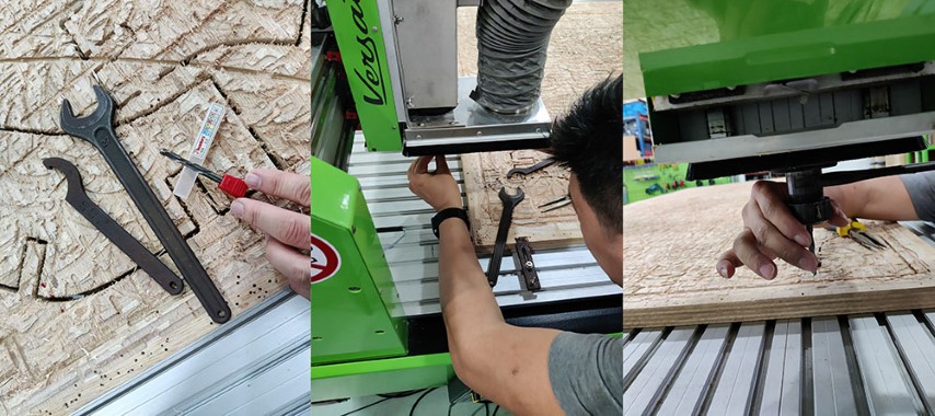
3) Z-axis calibration after changing the drill bit. This step is to prevent the Z-axis over-run either to the top limit, or bottom limit to cut just slightly after the sacrifition board.
Generating G-Code using VCrave-PRO software
After open the file, you may need to --> Stock's size and thickness --> X-Y Position --> Press OK button to enter the DRAWING Section.
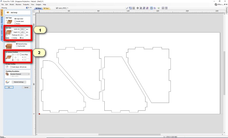
In the DRAWING section, there are 2 things that you need to do before send for toolpaths generating (refer to side tables at the left)
1) Under Join Vectors tab, select all the polylines and join all them by clicking the JOIN button. This is to ensure that all the OPEN loops lines are closed to generate the milling path.
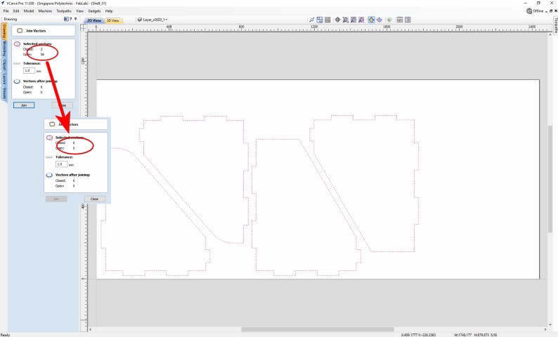
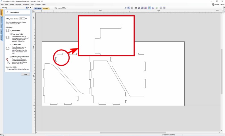
2) To ensure that the joints and slots are fully press-fit, I have generated Dog-Bone Fillet on all the inner corners for all parts. The value of the radius should be 3mm, as we are using a 6mm diameter end mill.
Once these 2 processes are done, we may click on the Switch to Toolpath Command button to start program the toolpath for my parts.
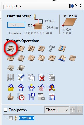
Under the Toolpath Operation, there are a lot of operation you can select to cut/mill your stocks. For my case, I will select PROFILE Toolpath to vector cut out my parts.
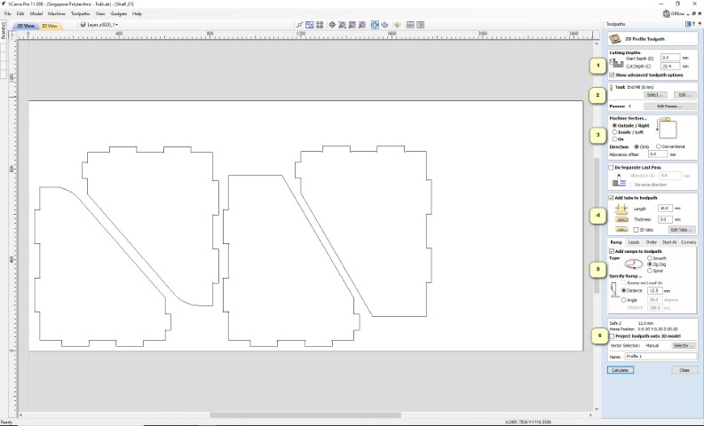
Under 2D Profile Toolpath, here are the figures that we need to input in order to generate the profile toolpath:
1) Cutting Depth - Start depth = 0mm (on material surface), Cut Depth - 24.4mm (measured material thickness) + 0.6mm (added value to cater material wrapage) = 25.0mm
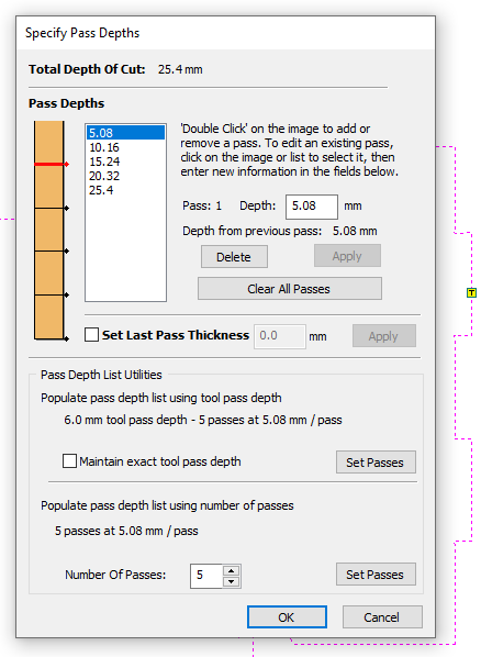
2) Tool - Press EDIT and will lead you to a seperate page to select a drill bit size and input the respective setting. Passes refers to the number of cycles that the end mill required to cut down the required depth. In this case, the value for the passes = Round up value of (Cut depth/Pass depth) = Roud up figure of (25mm/6mm) = 5 passes.
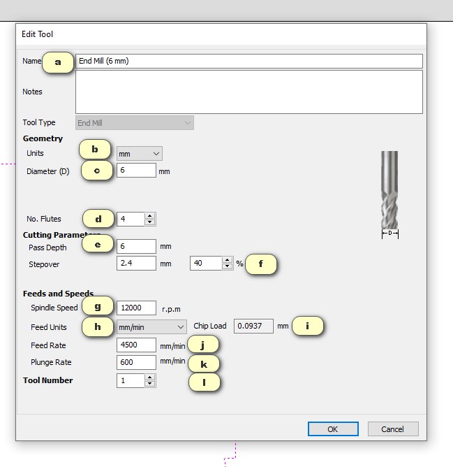
a) We choose End Mill (1/4") (equipvalent to 6mm end mill)
b) Unit = mm
c) Diameter (D) = 6 mm.
d) No. Flutes = 4 flutes.
e) Pass Depth = 6 mm (same as the tool diameter).
f) Stepover = 40 % (not more than 50%!)
g) Spindle Speed = 12,000 r.p.m. (can vary up to 18,000 r.p.m.)
h) Feed Units = mm/min.
i) Chip Load will be vary depending on 3 inputs: Number of Flutes, Spindle Speed and Feed rate. In general, there should be a datasheet given when you purchase the drill bit, but we can also set any figure that made the chip load have a value of 0.025mm ~ 0.25mm.
j) Feed Rate = 4,500 mm/min, which have a chip load value of 0.0937mm (falls within the allowable range).
k) Plunge Rate = 600 mm/min (the speed that allows the drill bit drill into the material).
l) Tool number = 1 (no tool changing option).
3) Machine Vectors - we select Outside/Right so we don't lose material at the borders while milling.
4) Add Tabs to Toolpath - Length = 10mm --> Thickness = 3mm --> Edit --> Add tabs manually. This step is fairly important, as the tabs will help to endure that the cutting parts are still intact with the stock even most of the polylines have been cut through, especially for those small cut-outs.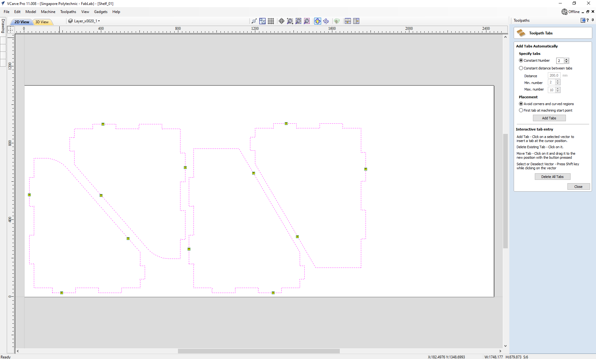
5) Add Ramps to Toolpath - Zig-Zag ramps are being selected, as we want the drill bit to mill down with a gradient and do not wish to damage the material surface by direct plunging into the required depth.
6) Rename your profile cut and click Calculate to generate the toolpath.
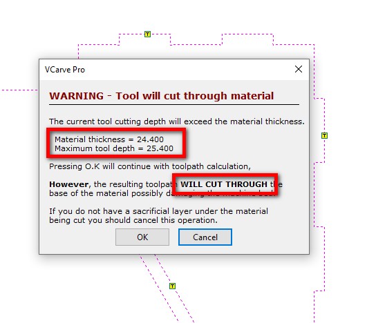
Oh No!! Error occurs before the software starts to generate the toolpath G-Code.This is because the cutting depth (25.0mm) was more than the material thickness (24.4mm). Not to worry, our machine has a "Sacrifition Plywood" to let the machine cut through the stock and yet won't damage the machine bed.
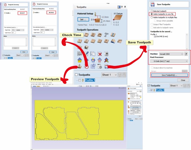
Once confirmed (Press OK), the software allows us to preview the toolpath. We could also check how much time the toolpath takes to estimate our process time. You may save the toolpaths by ensuring the below details are correct: --> Visible toolpaths to one file. --> Check the toolpaths. --> Machine = Versetil 2500. --> Post Processor = G-Code (mm) (*.tap) --> Save Toolpaths(s).
CNC Milling using NC-EAS(Y) Pro software
I open the G-Code using a CNC Program Printer named NC-EAS(Y) Pro. Even though it is a different machine software from what I have learnt in the past, but the basic concepts are similar:
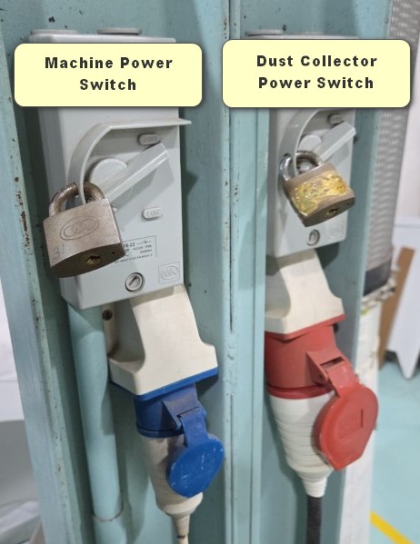
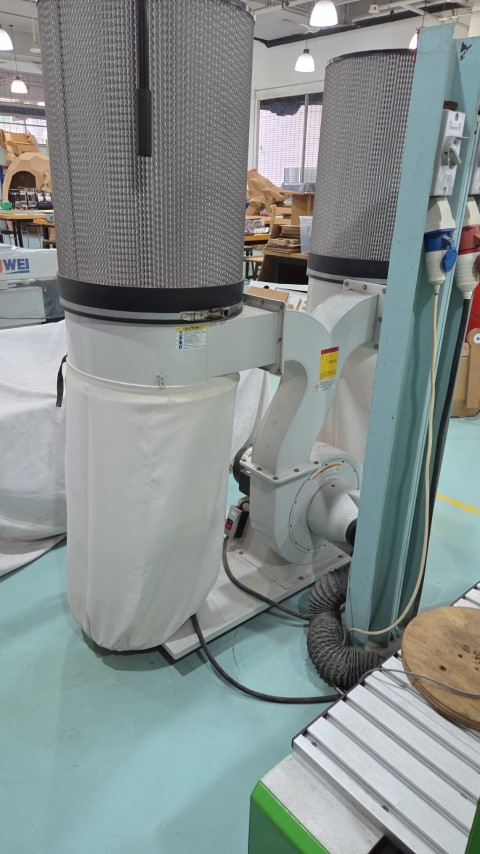
1) Turn on main switches for both machine and dust collector.
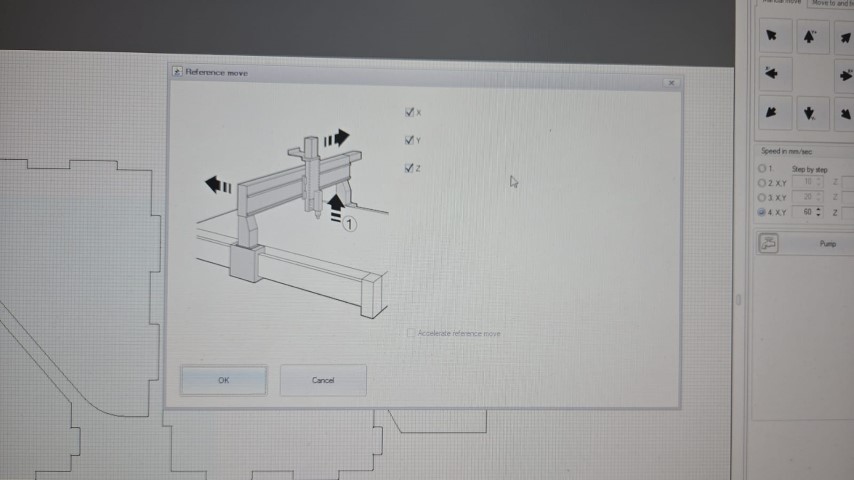
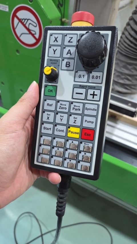
2) Reference the tool head (Auto prompt).
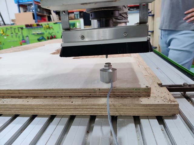
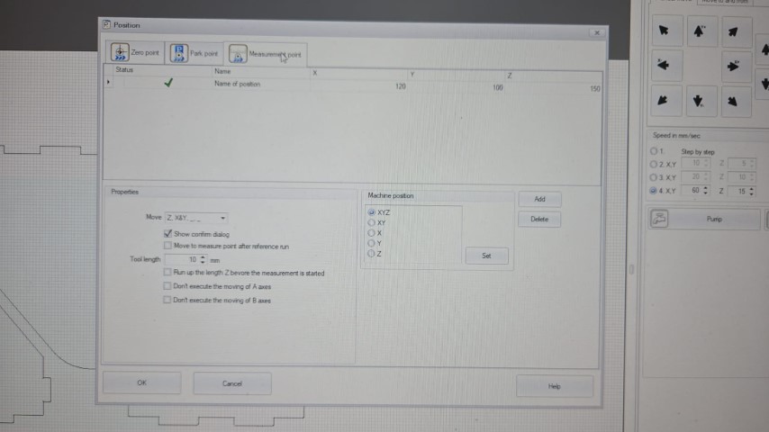
3) Move the tool head to the Measurement Point and determine the material thickness by using the tool sensor.
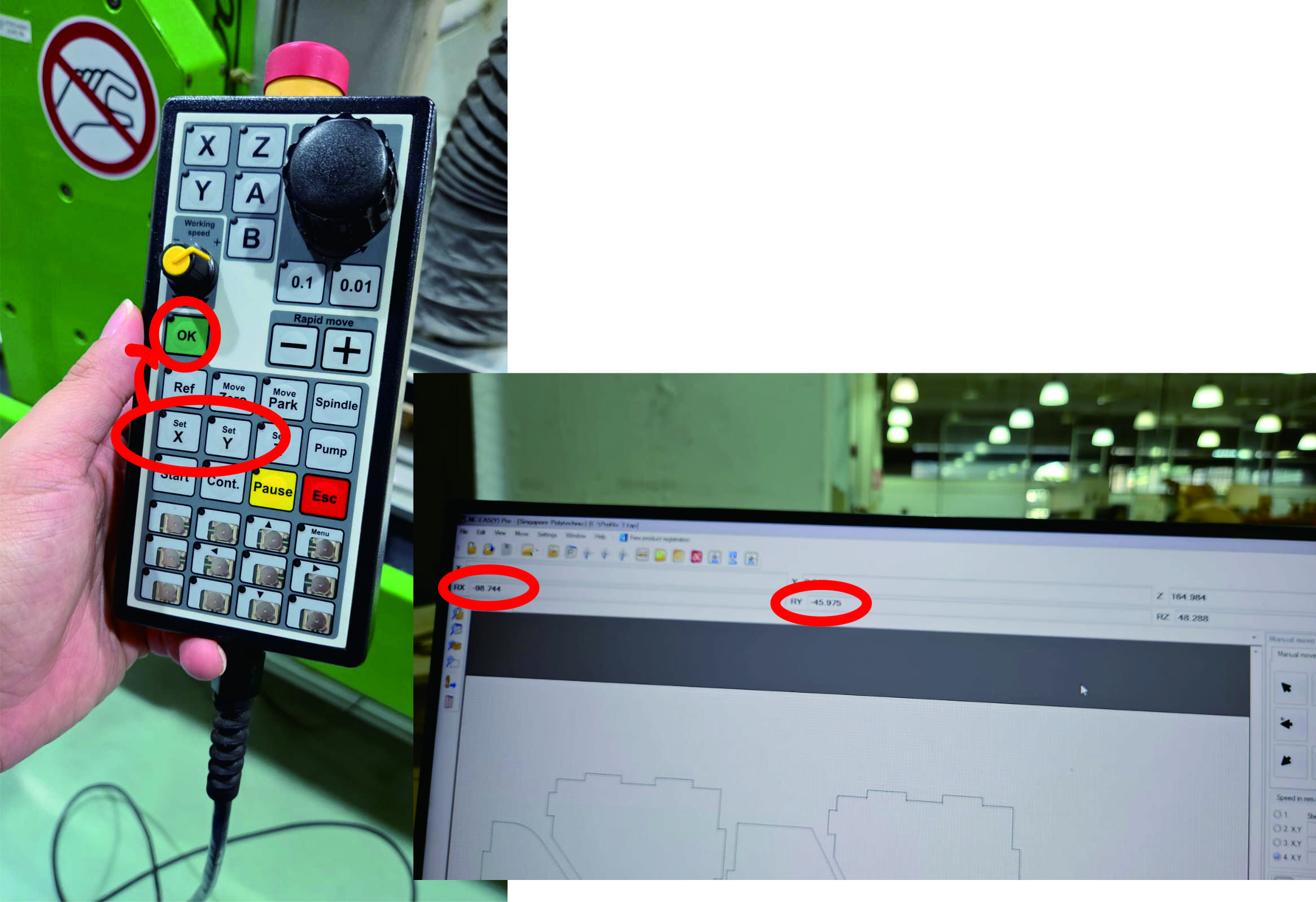
4) Set both Reference X point and Reference Y point by moving the tool head to the point that you set as material origin --> Press "Set X" button --> Press "OK" button --> Press "Set Y" button --> Press "OK" button. Then both RX and RY will become ZERO.
5) Toggle the tool head to the other end of the point to ensure that all the cutting parts fall within the stock size.
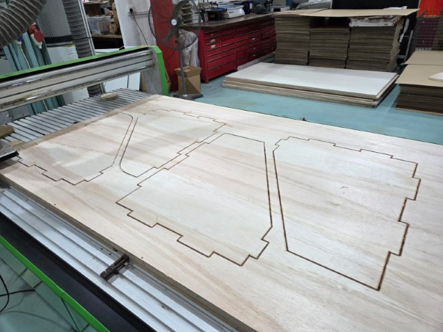
Once all these steps are done, we may start to run the machine. 2 important things need to take note:
1) Always switch on the dust collector before the machine starts to run for operation.
2) Always has the hand-held controller in hand just in case for the emergency button.
It tooks approximately 1.5 hours to mill 2 pieces of the 25mm 4' x 8' plywood.
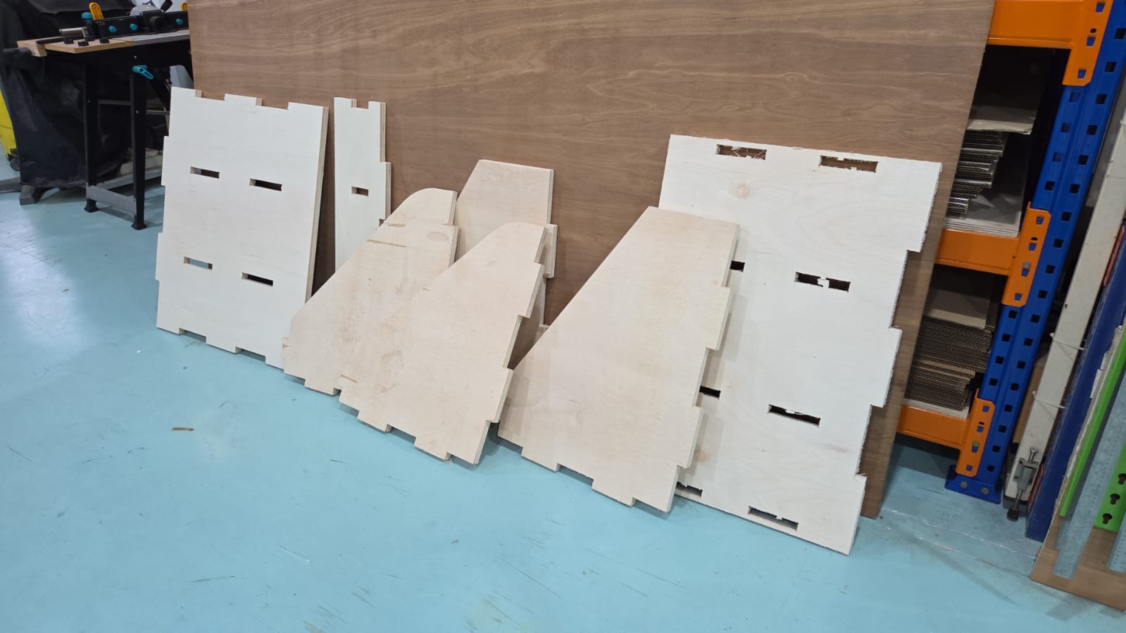
Post Processes - Surface Finishing and Assembling
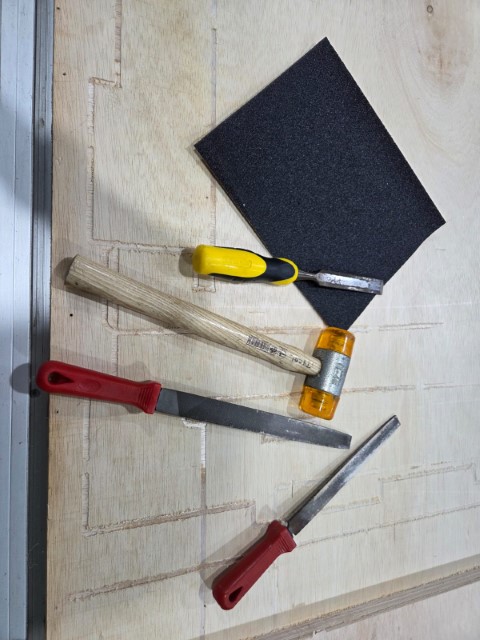
After finish cutting all the assembly parts that I needed, I uses chisel to remove the leftover piece for the tabs and uses diamond files to smoothen the surfaces and edges of the parts. For some surfaces, I will use sendpapers to remove all the stringy hairs.
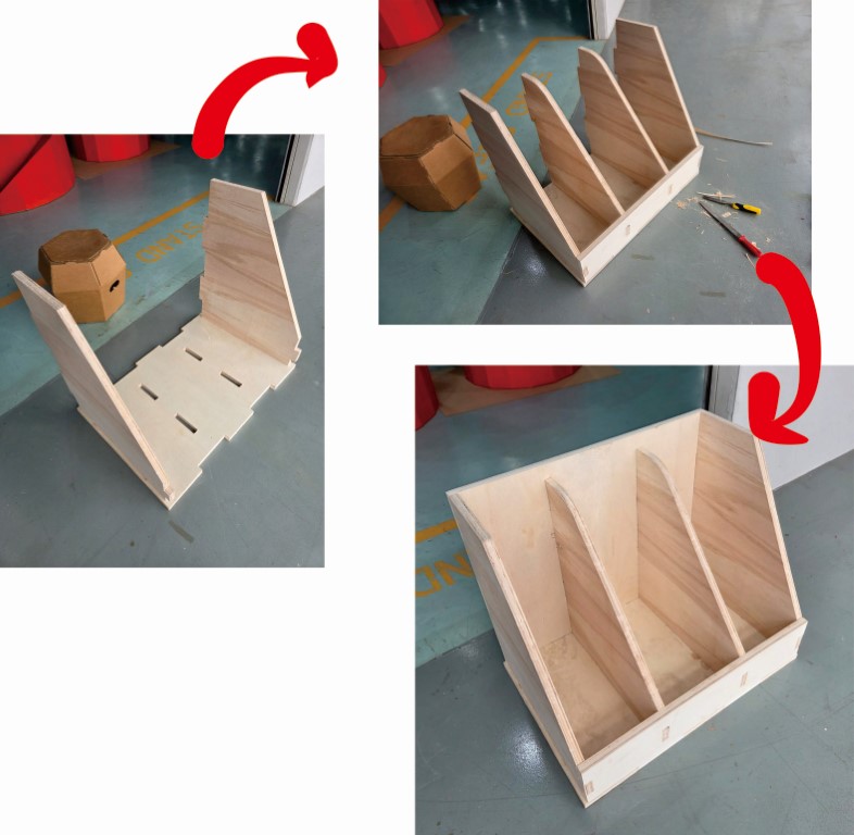
The moment of truth has come, I am now going to put all the parts into the model that I was designed earlier. Here it goes:
Reflection
It was a fun week for me to go along from the start of the process - the designing of the storage unit, until the end product was born. Not a difficult topic for me to master, as I have experienced a similar working process before joining Singapore Polytechnic FabLab.
But still there is ONE BIG THING that need to keep in mind as a reference for future use - Always cater a bit more space for those areas that require joining together, approximately 0.3mm ~ 0.5mm per edge. This would make your life much more easier when undergoing the assembly process. I have to chisel out some small portion on the finger joints, or even tare out a thin surface of the plywood, to allow me to fit all the joints.
I will modify my design with an add-on top shelving after this course to make my storage unit more complete.